Friday, January 6, 2012


Thursday, January 5, 2012
LC passive circuit

notch filter

AC sweep

bode plot
bandwidth is very narrow.

looks like low pass filter

except it resonate near (LC)^-0.5

at resonant frequency, output goes unstable.
Wednesday, January 4, 2012
log amplifier, exponential amplifier, precision amplifier

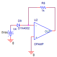
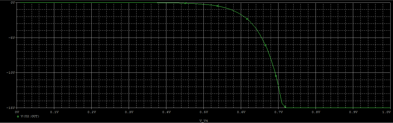
log amplifier with diode

dc sweep log scale linear
Vout = -Vt*ln(Vin/(Is*R)), Is saturation current of diode.

log amplifier with transistor

dc sweep log scale linear
exponential amplifier
linear scale exponential
Vout ~ -R*Is*exp(Vin/Vt).

full wave rectifier

~1.4v drop across diodes

pricision rectifier
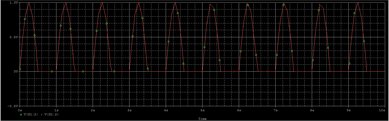
rectifier with no voltage drop on diode
Monday, January 2, 2012
bistable, astable, monostable circuit
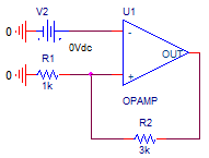
bistable


dc sweep 10 to -10v, transition happens at (L-)*[R1/(R1+R2)]. (L- amplifier supply V-, in this case -15v)

astable

excited with impulse, disturbing the banlance point at 0v, we got a viberator.Viberation period ~ R3*C1 = 0.1s

output is also 0.1s periodic. when output is positive, capacitor is charged, U1- increases till it hits the threshold (L+)*[R1/(R1+R2)]. Then output plummets to negetive, capacitor is discharged, U1- decreases untill it his the threshold (L-)*[R1/(R1+R2)]. Then output bounces to positive, capacitor is charged...

monostable
D5 is used to isolate V3 after the pulse goes through.

excited with positive pulse, U1+ is positive, (Uout - U1+)/R2 = U1+/R1, Uout = [(R2+R1)/R1]*U1+, Uout is also positive. D4 is reversely biased, and is like an open. Capacitor is charged. U1- increases untill it hits (L+)*[R1/(R1+R2)]. Then Uout plummets to negative. Capacitor is discharged. U1- decreases to -0.7v. Diode is foward biased. U1- can decrease no more. Circuit becomes stable.
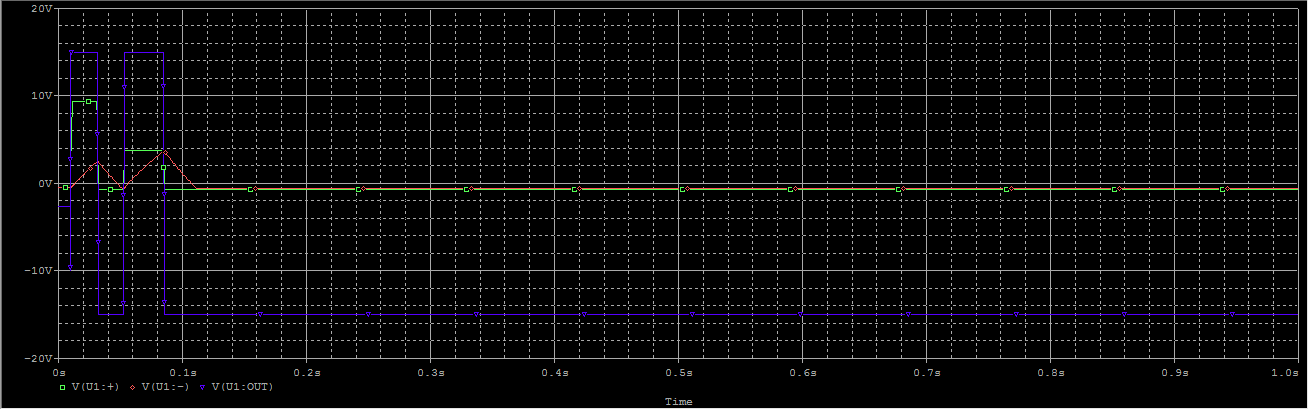
Even with high energy pulse, after a jerk, Vout settles down.
Sunday, January 1, 2012
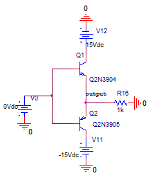
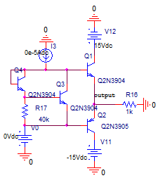
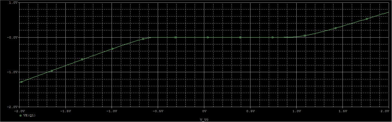
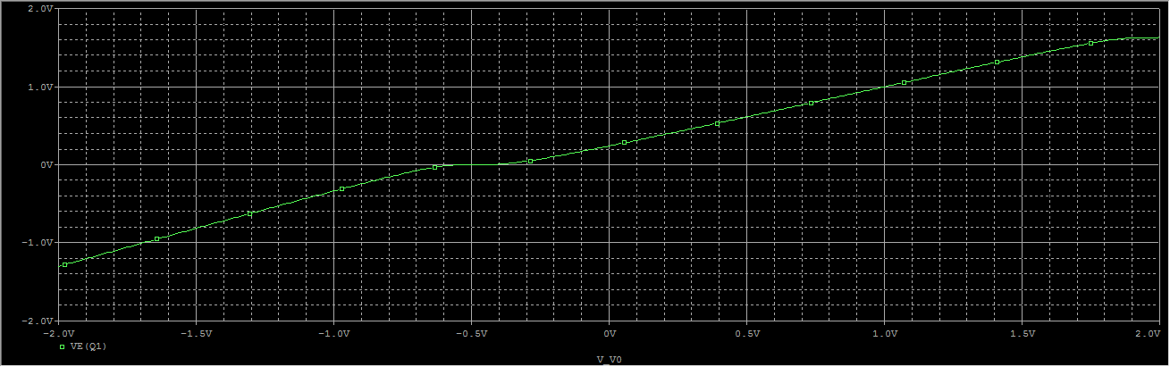
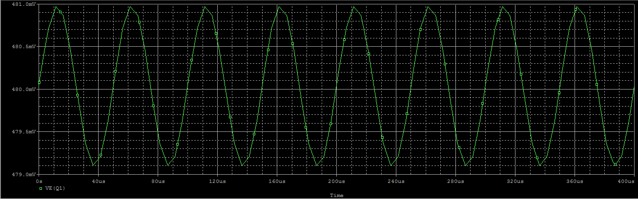
cross-over distortion


Subscribe to:
Posts (Atom)